| Advancements In Lost Foam Prototyping
Fabricated foams offer flexibility in prototyping new Lost Foam designs. Also, new methods of making machined aluminum prototype tooling offer advantages over other prototyping methods.
Fabricated Foam Patterns
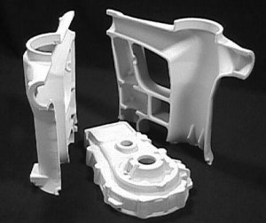
Using methods adopted from other manufacturing operations, Lost Foam patterns can be constructed and used to prototype cast parts. Castings made from fabricated patterns are currently being used to test parts for automotive engines and accessories, HVAC compressor design, heavy truck engines and small engine innovations. In each case, these have succeeded because of the ability to cut complex passages, accurate glue lines and to incorporate features that will later be made with production tooling. The primary method to produce a fabricated foam pattern is directly cutting from three-dimensional CAD data.
Prototype Part Design
Manufacture of the fabricated foam pattern begins with customer 3D data. The data is modified to represent the final, tooled Lost Foam part including draft, stock and glue lines. After the parting lines are determined, the part data is split to represent the individual foam pieces that will be cut. These pieces will later be assembled to produce the final, prototype part.
As the fabricated foam prototyping method was being developed, it was decided that strict adherence to final part features would provide the greatest benefit to the customer. This creates fabrication methods that most closely replicate future production and assembly methods.
Form-fit-function issues that arise from draft and parting lines often make it necessary, in other prototyping methods, to sample designs several times if these features are not considered on initial parts. In addition, features such as radii and draft are commonly left off in other methods and this affects aspects such as the strength and castability of the part.
CNC Cutting Methods
The machinery used to produce fabricated foam patterns is adapted from CNC equipment available on the market with features to improve cutting accuracy and speed. Waste removal fittings were also added to the machinery to maintain clean cutting surfaces and to recycle material.
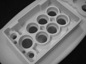
Special cutting tools were developed with each innovation requiring a different combination of cutting methods. The most challenging cutting task, currently, is the capability to cut small features in deep pockets. While success has been achieved for prototyping purposes, this is an area that will continue to be developed.
Fixturing is unique in this process due to the properties of the foam material. Foam fixtures require more elaborate and innovative support methods to guard against distortion and breakage during the cutting process.
Foam Pattern Assembly
Often, due to features that are required in the customer part, a pattern must be split into pieces that can be directly cut and then assembled to create the final pattern.
The individual pattern pieces are assembled using airset glue developed specifically for use with the foam material. The adhesive has characteristics, which provide glue filling, strength, and yet does not degrade the foam material or adversely impact the casting process. Gluing typically requires fixtures to provide weighting and accuracy to insure a good seal.
Part Complexity Possible with Fabricated Foam Methods
Parts can be extremely complex in the fabricated foam process as is the case with all Lost Foam casting methods.
Parts such as engines heads, exhaust manifolds and pressure valves have all been successfully prototyped and cast. Casting walls can be any thickness that is normally formed with Lost Foam tooling. Glue lines are typically the same as production patterns, except in large parts, which may require added glue joints for construction.
Complexity, in fact, is often a reason for selecting fabricated patterns. A similar complex part made in production tooling requires multiple tool cavities, moving tool features and several setups to mold patterns pieces. Starting with production tooling methods without the benefit of what can be learned from the prototype part design is cost prohibitive, especially when realizing that most early designs are subject to significant change.
Starting with fabricated foam pattern methods, all potential design characteristics can be produced, analyzed in the casting and accepted or rejected without the need to produce any tooling.
Pattern Costs Using Fabricated Foam Methods
Typically, the cost of fabricated foam is similar to other prototyping methods, such as, SLA (Stereolithography) and LOM (Laminated Object Manufacturing). The significant difference between these methods is that fabricated foam patterns may be used to directly produce castings after they are used as visual tools and engineering models. There are no added process steps other than what is normally required to cast a Lost Foam part.
The cutting time and engineering must be factored in to each piece produced, which makes the cost of a fabricated foam pattern significantly higher than that of molded foam patterns. For this reason, a common economical quantity limit of 15 to 20 patterns can be expected before a machined aluminum prototype tool becomes a more viable option.
Advantages of Fabricated Foam Patterns
Flexibility of design is the key reason to consider fabricated foam methods. With CNC cut fabricated foams, changes can be made as often as required without the need for tooling modifications.
Timing is a second critical advantage. Since changes are made to the model data and not to any tooling, turnaround time can be as quick as 3 to 7 days to produce a new pattern and have it cast. This requires good, accurate CAD data from the customer.
Fabricated foam patterns are the only direct to casting prototyping method. Other prototyping methods require investment-casting methods to be employed, which increases the cost of producing an actual casting.
An often-understated advantage of the fabricated foam process is that it most closely replicates the actual Lost Foam casting production process. This allows designers, pattern producers and foundries to gain knowledge about the part and any casting concerns, which can then be averted in the production process.
Machined Aluminum Prototype Tooling
Machined aluminum prototype tooling can rapidly produce accurate, quality molded patterns to allow a foundry to cast initial and pre-production part samples and develop the casting process. Castings produced with prototype tooling have been used in the automotive, large diesel engine, small engine, hydraulic valves and many other markets. Quantities cast have ranged from 20 to thousands of pieces.
Manufacturing Process for Prototype Tooling
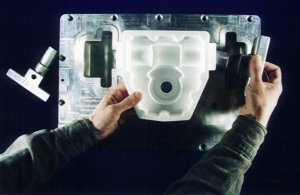
The preferred process used to manufacture castings with prototype tooling begins with the completion of a three-dimensional model. The accuracy of customer data and the changes made to the design to tailor the part to the Lost Foam process are critical. Also, foam and metal shrinkage factors must be incorporated into the model at this point. After the model is complete and approved, there are two prototype tooling options available:
- CAD data can be split to make the necessary pattern pieces that will be assembled through gluing. Translated CAD data is then used to cut the tool cavities directly. Using this method results in the most accurate and, generally, the fastest method of producing prototype tooling.
- CAD data can be used to produce a master part model, which is manually split into the required pieces. The resulting pieces are reversed using standard pattern shop methods and cast epoxy takeoffs are generated to produce master duplicating models. This method is slightly more time consuming and has a greater possibility for inaccuracy. It may be, however, the only option available when attempting to replicate an existing part or a part for which no complete CAD data exists.
In either case, it is often advantageous to make a prototype model, such as a fabricated foam pattern, to use in reviewing the part and modifying the features to be produced.
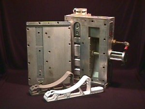
With the part model prepared for use, the construction of the prototype tool begins. Each pattern piece requires a set of matched cavity plates to be machined. Typically, two or more of the pieces can be included on one set of plates to produce the whole part. The plates are designed to fit into a receiver chest which eliminates the time and expense required to make the tooling fit a specific machine and provide steam, water and air for the molding process. The receiver chest is equipped with all of the required utilities and is designed for use on a variety of molding machines.
Tool plates are prepared by machining locators for the final mold chest layout, sealing surfaces and mounting holes. The plate is located in the CNC (or duplicator) and is machined with the most rapid methods available. Differences between prototype machining and production machining include, higher cutter speeds and feed rates, less work on non-critical detail areas and less attention to the stresses introduced to the tool by the machining process. This results in minor differences between the prototype molded foam and the production foam, particularly with the quality of the surface finish.
For parts that contain a feature that must be made using a core pull, two options are available:
- The pattern can be made in more sections to eliminate the need for the pull and glued together to replicate the feature. This causes a difference, however, between the prototype part and the final production methods.
- Manual pulls may be designed in the tool and offer the opportunity to make the part as close to the production configuration as possible.
Pulls must be heated and cooled along with the rest of the tool and a means to remove the pull from the tool and the foam pattern must be established. The cost of the additional pull operation compared to the need to exactly reproduce the production part will be the determining factor. Generally, it is advisable to exactly replicate the production pattern configuration.
Final tool construction processes consist of installing vents, establishing fill locations and cleaning and polishing the tool. The tool is then placed into a receiver chest and the two mold plates are referenced to each other and bosses are included to support the tool against the stresses of the molding operations.
With good, accurate customer CAD data a machined aluminum prototype tool can be delivered in 3 to 4 weeks. If CAD must be corrected or generated or if duplicating models are to be used, delivery time will vary from 4 to 8 weeks.
Pattern Molding with Prototype Tooling
Foam pattern molding using prototype tooling is very similar to the process used in production tooling and uses the same foam molding equipment and processes. With machined aluminum prototype tooling, unlike cast epoxy tooling, sintered metal or spray metal, no extra care is needed over what is required with production tooling.
The resulting foam patterns require similar curing time and gluing as production foams. Often, simple glue nests and fixtures are used to ensure accurate and consistent pattern assembly. The foam pieces themselves may also be molded with pins and holes included to help align the pattern during gluing. If glue lines are flat, universal gluing plates can be used to assemble the pattern pieces. For more complex, contoured glue printers may be used along with more sophisticated alignment fixtures.
Pattern Costs with Prototype Tooling
Using machined aluminum prototype tools to produce molded foam patterns in a standard foundry pattern molding environment will result in patterns with a higher per unit cost than production tooling and a lower per unit cost than fabricated foam prototyping.
The total price of patterns from prototype tooling, however, should be calculated as the cost of the tooling plus the cost of setup and molding. For this reason, the best prototype tooling applications are when short pre-production runs of 20-100 pieces are required. At these volume levels, the combination of two factors, price and delivery time, favor the use of prototype tooling methods over other methods including fabricated foam prototyping.
Advantages of Machined Aluminum Prototype Tooling
Machined aluminum prototype tools are extremely accurate and can reproduce a pattern hundreds to thousands of times with no loss in pattern quality. Often approved cavities in the prototype tools can be reconfigured to run as part of the production tool itself with minimal redesign and cleanup.
Tooling is designed to run in designated receiver chests, which eliminates the need for any special mounting or molder safeguards other than what is commonly practiced with production molding processes.
Prototype tooling is easily revised to allow for design changes, as a part is being tested and configured. Welding, inserting, cutting and grinding operations may be performed on the tooling eliminating the need to replace an entire tool set and without compromising the integrity of the tool.
Summary
Choosing a prototyping method to produce castings in Lost Foam depends on the objectives of the project.
Fabricated foam patterns using CNC cutting methods can be remarkably cost effective on complex part designs that are subject to revision. Fabricated foam processes provide the best value for low-volume pre-production runs when design changes are a consideration. Typical lead times are two to three weeks to receive a sample casting provided good CAD data is received or generated.
Most importantly, fabricated foam patterns offer the only direct to casting method available. They can be used in place of other rapid prototype modeling parts for reference and visualization and then still be used to make a prototype casting.
Machined aluminum prototype tooling is more effective than fabricated foam for higher volume runs with more stable designs. In addition, prototype tooling replicates many of the production methods that will be employed at a later date and provides an opportunity to collect data on the process methods.
Typical lead times of 3 to 4 weeks for prototype tooling and one to two weeks for ready to cast sample patterns are attainable.
Development of fabrication methods for foam patterns and machined aluminum prototype tooling are assisting designers of Lost Foam castings in bringing their ideas to the market more rapidly.
|