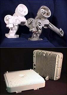
Oil Filter Adapter production foam and machined casting (top) and Communications Network Signal Transmitter Housing production foam and finished
casting (bottom) |
First Annual ECS Casting Contest Showcases Lost Foam Casting Design Successes
Lost Foam casting projects are garnering more attention due to recent industry-wide recognition. The success of two Lost Foam casting projects are detailed in this month’s Feature Article.
Oil Filter Adapter Component for a Heavy Diesel Engine Manufacturer
The oil filter adapter part is an aluminum alloy casting supplied by The Maco Corporation of Huntington, Indiana.
To maximize the value of the Lost Foam process, several goals were set at the beginning of the project, including:
- Combine as many of the existing iron and aluminum components (six total) as possible into a single piece aluminum casting.
- Provide maximum weight savings.
- Eliminate need for cores.
- Improve mechanical properties by eliminating leak points and mechanical joints.
Prototype and test the design prior to production runs.
Austin Design Group, Inc. was enlisted to assist in tailoring the part design to the lost foam process and to provide prototypes. Initial review of the design revealed that many draft areas could be reduced thereby decreasing the amount of machining that would be required on the finished casting.
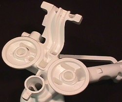
Production parting lines were developed and used in the Fabricated Foam prototyping phase to prove design and casting processes. |
In addition, Austin Design Group, Inc. determined the parting lines that would be required in order to incorporate all of the complex internal passages and cast-in holes.
A complete three-dimensional model was constructed using existing data from prints and the features needed for the Lost Foam process. It was important for this project to have a single 3D model to work from in order to ensure that prototypes, tooling and production parts would all be consistent.
After consulting with the end user, a decision was made to use Fabricated Foam Prototypes to prove out the design. Initially, four fabricated prototypes were made by Austin Design Group, Inc. and cast by The Maco Corporation. These prototypes were used in field test conditions and design changes were initiated based on their performance. In all, seventeen prototype patterns and castings were made during four phases of design changes. Each phase of the prototype production was completed in two to three weeks. All of the prototype parts were used in real-world conditions and provided valuable knowledge in assessing the part design. The final part design and the approval to proceed were based on the results of the prototyping phase.
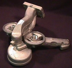
Initial run of production-level castings produced accurate and mechanically sound parts with no revisions required.
|
The next phase of the project encompassed designing and building the production tooling and glue fixtures. Austin Design Group, Inc. designed the production tooling and fixtures in accordance with foam molder machine and tool specifications. The design team and the foundry selected the tool builder. The production tooling was built according to the final designs and the foundry set delivery. The production tooling and fixtures were constructed in 12 weeks.
A first run of twenty-eight (28) production castings was produced to check dimensional accuracy and mechanical integrity of the part. In the first run of production castings, nearly 400 dimensions were
checked on each casting. No dimensions were found to be out of tolerance. Also, no leaks were identified in the first production run or subsequent runs.
As designated during startup, the following project objectives were met:
- Combined all six iron and aluminum parts into a single piece aluminum casting.
- An overall weight reduction of 48 pounds was achieved.
- No cores are required in the casting process.
- All production castings passed leak inspections during first casting run.
- By using fabricated foam prototypes, critical design elements were refined without any additional tooling cost and the part was field tested prior to production runs.
Signal Transmitter Housing for Wireless Communications Network System
Signal Transmitter Housing for Wireless Communications Network System
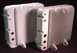
Specialized tooling methods were developed that allowed long, thin cooling fins to be cast successfully.
|
The transmitter housing part is an aluminum alloy casting supplied by Willard Industries of Cincinnati, Ohio.
The part contained several challenging features, including:
- The end user requested a single-piece casting with no glue lines.
- Cooling fins that are 0.120” thick by 1.25” tall and run the entire length of the part (approximately 15”)
- Uniform wall thickness of 0.160” held throughout the part over distances of approximately 16”
- An interior deck surface held to a .010” tolerance over a 15” by 15” square area
- A flanged mounting surface incorporated into the part without splitting the foam pattern into sections.
- The two halves of the part held to a critical overall height to ensure that electronics components added during final assembly all fit into the completed equipment.
- Provide an overall weight savings and machining reduction by targeting minimum draft and stock.
Austin Design Group, Inc. was brought in on the project, initially, to help target the part to the Lost Foam process and to provide foam prototypes to prove out the design.
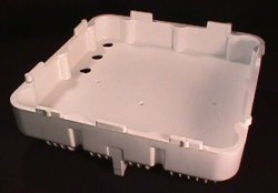
Mounting flange incorporated into
one-piece design.
|
If the design and the prototypes were successful, Willard Industries and the end user would work out a production tooling and casting schedule. Approximately ten prototype Fabricated Foam pattern sets were provided to Willard for preliminary casting runs. Foam patterns were fabricated in two pieces and glued together. Prototype pattern sets, ready to be cast, were provided within 4 weeks of approval of the 3D model by the end user. Based on the success of the design concepts and the prototype casting accuracy, the end user was able to meet UL standards and subsequently approved the production tooling phase. Austin Design Group, Inc. combined several specialized design techniques and tooling methods to produce the part in a one-piece foam pattern with all of the required features incorporated. Production tooling was provided in 12 weeks.
Overall, the following project objectives were met:
- Part is produced in one-piece eliminating the need for exterior glue lines.
- All cooling fins successfully cast to original design objectives.
- Deck heights held accurately for machining purposes.
- Flanged mounting surface incorporated into the one piece design.
- Casting weight was lowered from 16 lbs. to 14 lbs. through targeting minimum draft and maintaining wall thickness.
Results of the First Annual ECS Casting Contest will be published in the Summer 2001 edition of the Engineered Casting Solutions magazine. The magazine is published on a quarterly-basis by the American Foundrymen’s Society.
|

